

 |
 |
|
#1
|
||||
|
||||
|
I am currently running an AirNavSystems RadarBox ADSB Receiver connected to a 7 Segment Coaxial Collinear Antenna manufactured by DPD Productions in California (this is normally a 9 segment antenna, however Dave built a 7 segment version for me to fit US Postal Service requirements). A 10 meter run of LMR400 coax cable connects the two, and the antenna is mounted on a 3 metre mast on the arch of our roof. This current setup delivers 250nm consistently on the eastern side of the compass, and down to Canberra and out to Orange on the western side (reception on the western side is limited by the house next door). During periods of Tropospheric Ducting, this setup has received transmissions from as far out as 1,200 km (600 nm plus).
The project over the past couple of day was to try and build my own ADSB Coaxial Collinear Antenna using 2 metres of left over LMR400 coax cable from the above installation. The aim of the project was to provide a Northern Beaches ADSB site using a Kinetics box, in order to enhance the PlanePlotter MLAT environment for Sydney (my existing AirNavSystems RadarBox has very good reception but does not provide suitable data for MLAT). Inspiration for the project came from this article http://www.balarad.net/ and this YouTube video is also useful from a construction point of view. Calculations for this project are: The wave length of the signal is Lambda = C/F where C is velocity of the electromagnetic signal in a vacuum, i.e. c = 300 million meters per sec, and F is frequency of the ADS-B signal, i.e. 1090 MHz, this gives a wave length Lambda of 275 mm. The length L of each antenna element is half the wave length reduced by the velocity factor of the coaxial cable L=0.5*275mm*0.85=116 mm (I checked the velocity of propagation factor for my LMR400 and it was 0.85). There is no clear guidance on how many segments to use, more than 12 apparently does not improve reception, and more than 9 starts to get too long antenna wise. I cut 9 LMR400 coax sections 116mm long, plus 20mm at either end for the connection overlap (the exposed braid section in photograph two). The shielding braid and foil were removed to leave the centre core exposed. The segments are interlaced together as laid out in the second photograph, the core of one being connected to the shielding of the next. Because the core of the LMR400 is so thick, I had to file a bevelled end on the core so it would slip under black outer case of the next cable segment, and in contact with the shielding braid. It is important to check the electrical continuity of each segment join with a multimeter, as any shorts are difficult to find after the antenna is fully assembled. Each segment join was then covered with heat shrink for protection. Once the 9 segments were all connected together, I soldered 15 metres of RG58 coax to the first segment, and inserted the antenna into a 1.15 metre length of 25mm conduit. Each end of the conduit was then sealed with 25mm round rubber leg tips which fitted perfectly. I mounted the antenna on my existing mast, offset to one side and completely below the existing antenna. This was done to reduce any interference between the antennas - I am not exactly sure whether they will interfere with each other, however we have plenty of data from the existing antenna, to notice any drop in reception. The other end of the RG58 has a SMA connector directly onto the SBS-1 box, which is connected to a laptop running BaseStation and PlanePlotter. Compared to the small mobile antenna I was using, the reception has now improved at least five fold, tracking aircraft out to 200nm to the north and east. The only way to directly compare the AirNavSystems Radarbox and Kinetics SBS-1 boxes, and the DPD Productions antenna with my home built antenna, would be to run another LMR400 coax instead of the RG58 on the Kinetics SBS-1 box - a project for another day. Some of the tools and hardware needed for the project 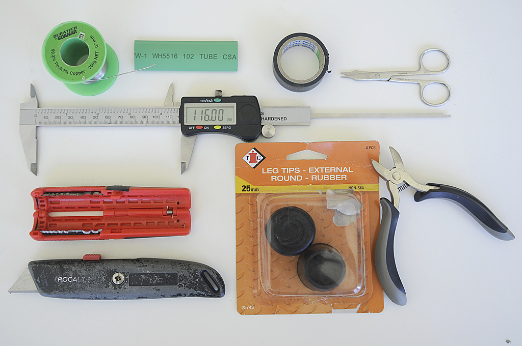 Shown here are 3 coaxial segment similar to the 9 in the finished antenna 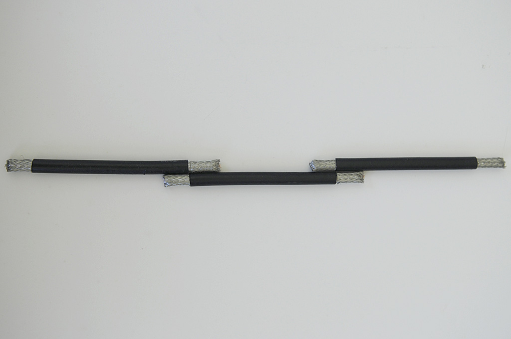 The existing DPD Productions antenna is located at the top of the mast, and my homebuilt half way up 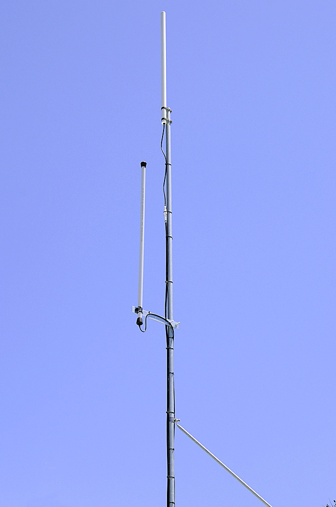
__________________
Joined 1999 @www16Right FlightDiary Airliners Web QR Retired PPL C150/172 PA28-161/181 Pitts S-2B SIM: 12Hr QF B767 B744 CX B742 Nikon D100-D200-D300-D500 Last edited by Grahame Hutchison; 21st December 2014 at 03:54 PM. |
|
#2
|
||||
|
||||
|
Thanks Grahame. Been thinking about making a collinear antenna for awhile. Wasn't sure of the formula. Looks like a New Year's project to try.
Have a left over length of LMR400 from the original ADS-B antenna installation that will come in handy. Will be interesting to see what improvement the LMR400 over the RG58 feed does to your setup. Happy Christmas,
__________________
Cheers, Noel White |
|
#3
|
||||
|
||||
|
Merry Christmas to you and your family Noel.
Let me know if I can be of any assistance with the antenna build (I had a few attempts with the individual segment joins, before doing the actual build).
__________________
Joined 1999 @www16Right FlightDiary Airliners Web QR Retired PPL C150/172 PA28-161/181 Pitts S-2B SIM: 12Hr QF B767 B744 CX B742 Nikon D100-D200-D300-D500 |
|
#4
|
|||
|
|||
|
When I had set-up T-YSWG2 using the USB dongle, I made quite a few antennas using sites such as http://www.balarad.net for ideas and using RG6 Coax (couldn't get my hands on RG58 nor LMR400). I've found the 8 element to be far more less susceptible to noise, 12 elements can get better range but also more noise (with the dongle, it doesn't handle it too well). Height of the antenna is also important (higher the better but a DA will be needed for anything 1.8m higher then the building).
My original 8 element (not 100% correctly made), which also lacked height. Set-up, the set-up was similar with the 12 element. 8 element range (Screenshot) 12 element range (Screenshot) To be honest, I have no idea if I was using a 8 or 12 element, but I did relocate the antenna slightly more to a clearer spot but also with a little more height. Set-up Range (Google Maps) My very last build so far us the 8 element CoCo with 68mm spike. Antenna set-up Range(Google Maps) Since hosting a FR24 box, I haven't really being using the USB dongle as much for ADSB but I have been meaning to make a Airband antenna. |
|
#5
|
||||
|
||||
|
Thanks for the info Robert, you have some good consistent range on those polar plots.
This is my current Polar Plot (Orange) and that from another station (Purple) that is feeding data to our system. The house next door affects my reception to the west. Both these stations are using the 7 Segment Coaxial Collinear Antenna from DPD Productions in California. Location in respect to higher terrain can make a big difference to reception. My best reception was to the northeast during Tropospheric Ducting - 648.2nm (1,201.2km). All the data relating to our site (Orange) can be viewed at http://adsb.16right.com/analytics/ 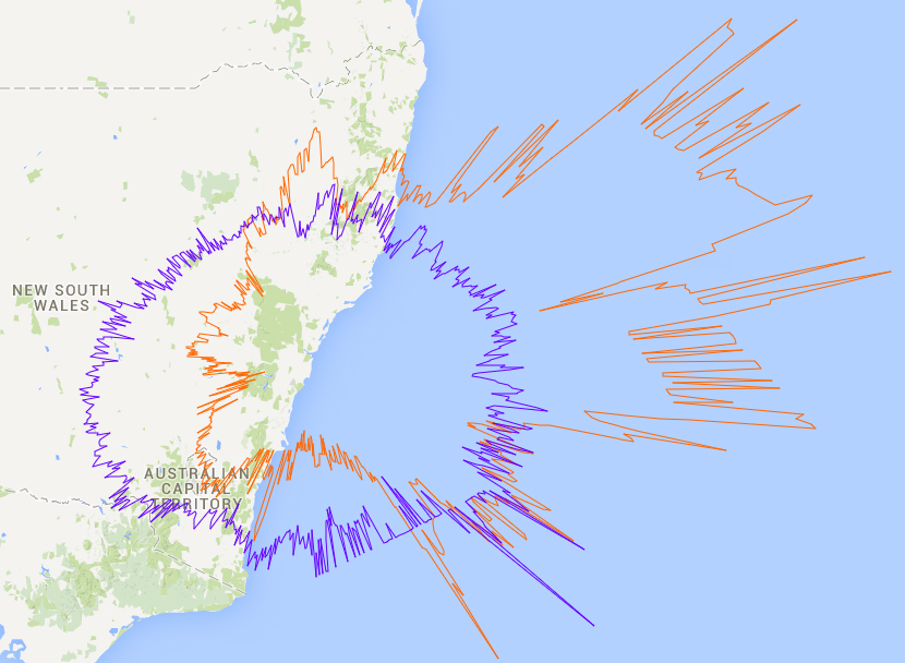
__________________
Joined 1999 @www16Right FlightDiary Airliners Web QR Retired PPL C150/172 PA28-161/181 Pitts S-2B SIM: 12Hr QF B767 B744 CX B742 Nikon D100-D200-D300-D500 Last edited by Grahame Hutchison; 22nd December 2014 at 06:14 PM. |
|
#6
|
||||
|
||||
|
I have recently moved to a new location in the Eastern Suburbs with a great southerly aspect, and have been testing the DIY
Antenna I made at the end of last year. The antenna is just fixed to the inside of the south facing lounge room window (12th Floor), basically covering 090 Deg to 270 Deg (although the 1st Polar Plot below shows some good reception to the northeast as well). There is only one metre of coax cable from the antenna to the SBS box, which significantly reduces any signal loss. Falcon 900 N146EX at the bottom of the map is being received by this new antenna at a range of 262.7nm or 486.5km - FL450 helps with the reception. Best pickup so far has been 266nm to the south. The other aircraft on the map are being tracked by my Station on the Northern Beaches, and a friend's third Station in Sydney. 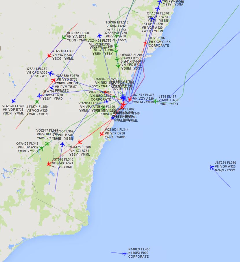 DIY Antenna Polar Plot 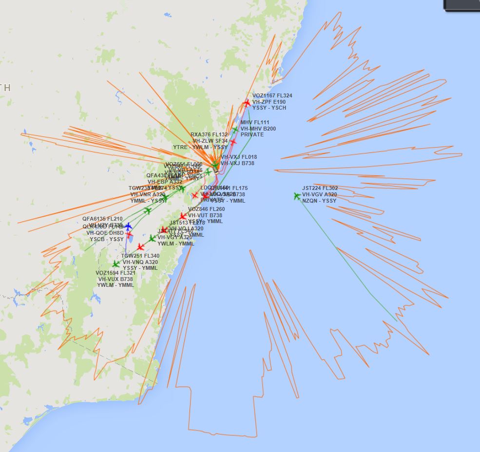 Our combined three Station Polar Plot covers 221,531nm² and the live map is available 24/7 at http://adsb.16right.com/live/map/ 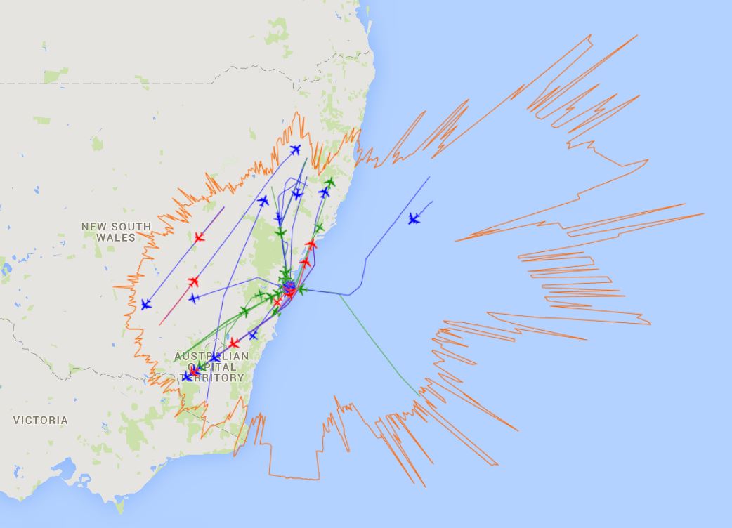
__________________
Joined 1999 @www16Right FlightDiary Airliners Web QR Retired PPL C150/172 PA28-161/181 Pitts S-2B SIM: 12Hr QF B767 B744 CX B742 Nikon D100-D200-D300-D500 Last edited by Grahame Hutchison; 17th July 2015 at 03:41 PM. |
|
#7
|
|||
|
|||
|
There's no hiding from you now, is there!

__________________
I am always hungry for a DoG Steak! :-) |
|
#8
|
|||
|
|||
|
Looks like it just reaches Wagga! Impressive range!
__________________
Robert Myers Photography - Aviation Spotting Australia Flightradar24 feeder (F-YSWG1 & T-YSWG2) FlightAware feeder (YSWG/6482) |
|
#9
|
||||
|
||||
|
I have added Wagga Wagga onto the Polar Plot, and yes, it is receiving out to Wagga Wagga Robert. Interestingly, the Airport just above the YSWG information balloon is
Parkes, which is on the Brisbane-Melbourne track, and this is being received through two apartments in our building. Best reception so far is 280.6nm at 132.5Deg, typically Corporate and Commercial aircraft on the Melbourne-Auckland sector. 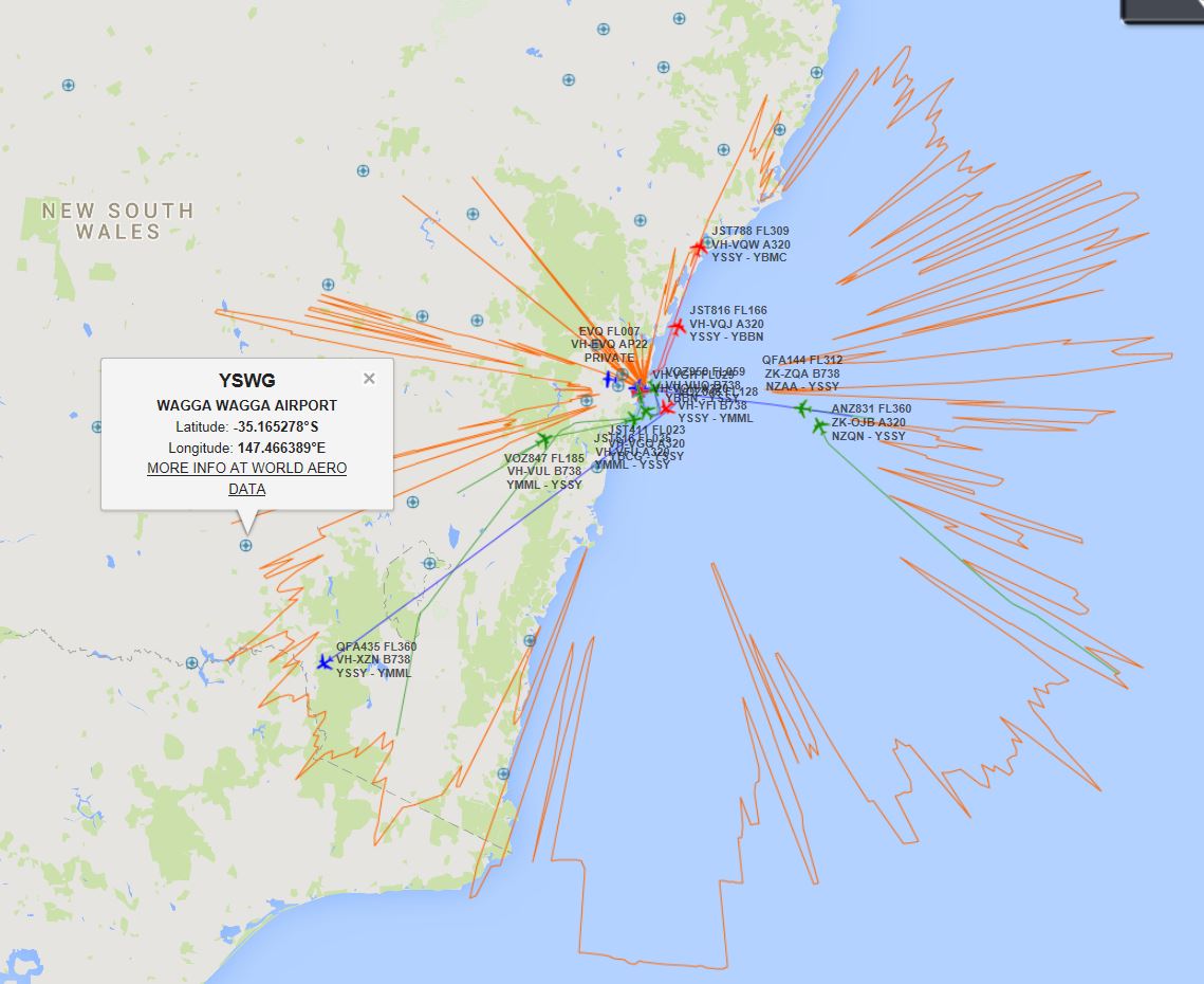
__________________
Joined 1999 @www16Right FlightDiary Airliners Web QR Retired PPL C150/172 PA28-161/181 Pitts S-2B SIM: 12Hr QF B767 B744 CX B742 Nikon D100-D200-D300-D500 |
|
#10
|
|||
|
|||
|
Impressive, sounds like you've got a lot of obstacles to deal with but still get good range!
__________________
Robert Myers Photography - Aviation Spotting Australia Flightradar24 feeder (F-YSWG1 & T-YSWG2) FlightAware feeder (YSWG/6482) |
 |
|
|